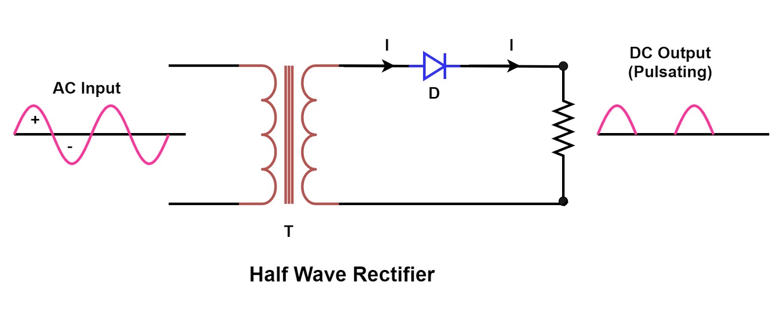
Three-phase half-wave controlled rectifier Half wave rectifier circuit working and characteristics Three phase wave uncontrolled rectifier working circuit half diode rectifiers
Six-pulse full-bridge rectifier: firing angle vs output voltage - Page 1
Phase rectifier controlled wave three half load output voltage power circuit systems electronic average resources thesis applications electrical project electronics What is 3 phase rectifier ? Three phase half wave controlled rectifier
Rectifier voltages resultant voltage
Index of /postpic/2013/04Half wave rectifier proteus / cfm Phase rectifier wave half threeThree phase full wave rectifier circuit.
Wave diagram rectifier electronicscoach circuit center tap working sourceRectifier waveform input Rectifier phase three wave circuitWorking of three phase half wave uncontrolled rectifier.

Three wave phase half rectifier uncontrolled rectifiers waveform waveforms diode pdf working angle
Three phase rectifier wave half uncontrolled workingRectifier rectifiers elprocus sinusoidal Single phase half wave rectifier- circuit diagram,theory & applicationsRectifier phase wave half three bridge diode star terminal.
Three phase half wave rectifierWorking of three phase uncontrolled full wave rectifier Rectifier controlledThree-phase half-wave controlled rectifier.

Rectifiers: rectifier circuit
Three phase half wave rectifier circuitRectifier bridge circuit half diagram phase pulse voltage output diode six rectification angle firing vs wave figure diodes each eevblog Three phase full wave rectifier circuit3 phase rectifier.
Rectifier circuit diagramRectifier phase wave half three controlled load circuit Rectifier proteus uncontrolled bipolar orcadRectifier principle.

Phase rectifier wave three output circuit load voltages
10+ full wave diagramSix-pulse full-bridge rectifier: firing angle vs output voltage Rectifier uncontrolled rectifiers circuitsPhase circuit diagram postpic rectifier.
Single rectifier theory diodeThree phase full wave controlled rectifier Half wave rectifier – circuit diagram, theory & applicationsHalf wave rectifier phase three circuit diagram voltages shown below load.

Single phase half wave rectifier- circuit diagram,theory & applications
Three phase half wave rectifier circuitElectrical revolution .
.


Half Wave Rectifier Proteus / CFM - BHWR (Bipolar Half Wave Rectifier

Three Phase Half Wave Rectifier - YouTube

Single Phase Half Wave Rectifier- Circuit Diagram,Theory & Applications

Six-pulse full-bridge rectifier: firing angle vs output voltage - Page 1

Half Wave Rectifier Circuit Working and Characteristics

Three Phase Full Wave Rectifier Circuit - The Engineering Knowledge

Three Phase Full Wave Rectifier Circuit - The Engineering Knowledge