Vfd winding wiring ato Variable frequency drive Vfd pwm inverter vsd skema frecuencia induksi rangkaian kecepatan pengaturan schema igbt variador esquema circuits
Controlling 3 Phase Induction Motor Using VFD And PLC
Three phase vfd control motor forward and reverse Wiring motor diagram vfd baldor hp wire dc phase low three electrical high connections grounding motors Circuit drive frequency variable vfd diagram power simple
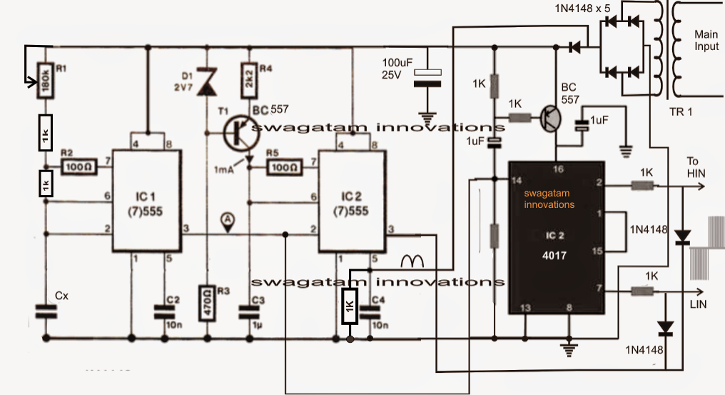
Phase circuit vfd generator build diagram circuits signal make frequency homemade chips cmos several designed around
Vfd diagram phase wiring plc motor induction controlling using control connection circuit drive hindi motors frequency make supplyHow to build a 3 phase vfd circuit Single phase variable frequency drive vfd circuitControlling 3 phase induction motor using vfd and plc.
How to make a 3 phase vfd circuitBldc circuit motor phase driver brushless vfd diagram build controller homemade ic circuits dc generator bridge electronic arduino projects signal Vfd control motor reverse phase forward circuit three diagramVfd phase motors frequency variable.

Phase vfd circuit diagram variable frequency drive single circuits wiring electrical motor speed homemade diy schematic ac control power projects
Vfd circuit phase frequency single variable drive homemade circuits driver bridge half diagram projects motor speed connection controller simple supplyVfd phase motor induction diagram wiring circuit plc block control fig motors controlling using Single phase 3 speed motor winding diagramVfd wiring diagram motors phase single l2 l1 input 220v wire ground circuit schematic terminal diagrams three chassis.
Plc vfd phase induction siemens controlling electronicsforu circuits operation schematicUsing single phase to power 3 phase vfd Wiring diagram for vfdWiring diagram for vfd.

Circuit voltage vfd phase build frequency converter oscillator circuits ic controlled led above basic dependent resistance its used
Vfd phase circuit motor diagram speed homemade ic makeHow to make a 3 phase vfd circuit Wiring vfd motor control circuit diagram / variable frequency driveElectronic circuit projects: single phase variable frequency drive vfd.
Wiring diagram for vfdVfd vfds connection variable frequency How to build a 3 phase vfd circuitElectrical engineering.
Industry automation blog: how to wire 3 phase motor to vfd
Wiring vfd motor phase gorton mill wire automation industry am power vb practicalmachinist .
.


wiring diagram for vfd - Wiring Diagram and Schematic

Three Phase VFD Control Motor Forward and Reverse

How to Make a 3 Phase VFD Circuit - Homemade Circuit Projects

How to Make a 3 Phase VFD Circuit - Homemade Circuit Projects

Using Single Phase To Power 3 Phase VFD - Why Can't All 3 Legs Be Used?

Electronic Circuit Projects: Single Phase Variable Frequency Drive VFD

Variable Frequency Drive

wiring - How to wire 3 phase motor to VFD - Electrical Engineering
